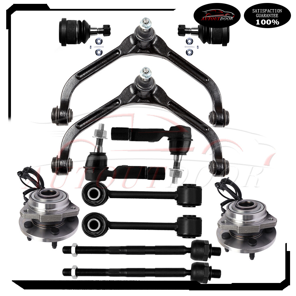
1.Fitting the Followingvehicle:2006-2007 Jeep Liberty2.Package Includes:1x Front Wheel Hub Bearing -5131761x Front Wheel Hub Bearing -5131772x Front Upper Control Arm And Ball Joint -K31981x Front Outer Tie Rod End - Driver Side -ES35351x Front Outer Tie Rod End - Passenger -ES35362x Front Sway Bar End Link -K73912x Inner Tie Rod End -EV8004162x Front Lower Ball Joint -K80767Tie-Rod End Replacement Guideline: For 2006-07 Jeep Liberty 12x Wheel Bearning Hub Sway Bar Control Arm Ball Joint
1.Fitting the Followingvehicle:
2006-2007 Jeep Liberty
2.Package Includes:
1x Front Wheel Hub Bearing -5131761x Front Wheel Hub Bearing -5131772x Front Upper Control Arm And Ball Joint -K31981x Front Outer Tie Rod End - Driver Side -ES35351x Front Outer Tie Rod End - Passenger -ES35362x Front Sway Bar End Link -K73912x Inner Tie Rod End -EV8004162x Front Lower Ball Joint -K80767
Tie-Rod End Replacement Guideline:
If you feel a bump in the steering when driving over road bumps or curbs, this might be due to worn tie rod ends or inner tie rods. Clicking noises during sudden steering movements can also be symptoms of a defective tie rod. In order to determine the exact cause and replace the defective tie rod, the car must be elevated with a vehicle lift in order to be examined more closely.
This useful tip applies to the exchange of tie rod ends and inner tie rods, which together form the so-called tie rod.
Picture(A)
Note: Cleanliness is extremely important when working on the power steering. Incorrect work and contamination can lead to leakage and, in the worst case, to failure of the steering assistance.
1.Lift the vehicle and dismount the front axle wheels.
2.Spray the fastening nut of the tie rod end with rust remover and leave it on for a few minutes.
Picture(B)
3.Dismount the front underride />4.Loosen the fastening nut from the tie rod and remove it completely.
5.Remove the tie rod end from the steering knuckle using an appropriate ball joint separator.
Picture(D)
6.Remove the clamp of the bellow on the steering gear.
7.Push the bellow towards the tie rod end.
Picture(E)
8.Unscrew the inner tie rod from the rack.
9.Clean the sealing face of the bellow at the steering gear.
Picture(F)
10.Clean the lug of the rubber contact surface of the ball joint in the steering knuckle.
Note:Always use new self-locking nuts and bolts for a reliable repair.
11.Screw the new inner tie rod into the rack and tighten it with the tightening torque that has been specified by the vehicle />12.Mount the bellow and close the clamps with the appropriate special tool.
Note:Incorrect mounting of the bellow can lead to corrosion of the rack: the steering gear starts leaking which can lead to a failure in the steering assistance.
Picture(H)
13.Secure the ball joint in the steering knuckle and mount the nut. Please observe the tightening torque suggested by the vehicle manufacturer.
Note:During mounting, the ball stud should not turn within the ball joint. This can cause damage inside the ball joint and can lead to early failure.
Tip:Secure the ball stud against twisting with a suitable tool.
Picture(I)
14.Mount the front underride guard.
15.Mount the front wheels and tighten them with the tightening torque recommended by the vehicle manufacturer.
16.Align the wheels and adjust them if necessary. Observe the vehicle manufacturer specifications.
17.Perform a test drive.
Note:When performing the test drive, pay special attention to the handling while cornering and listen for possible noise emission.
Ball JointReplacement Guideline:
If there is a knocking or clunking noise in the area of the front axle when the car is traveling over road bumps, potholes or curbs, then there is usually a defect in a component of the wheel side of the front axle from which the (vibration) noise is emanating can already be determined during a test drive. The type of noise also already provides certain indications for maintenance regarding which components might be />1.Raise the vehicle and remove the front wheels.
2.To loosen the fastening screws and fixing nuts of the compression ball joint more easily, spray them with rust remover and allow to act for a few minutes.
Picture(C)
3.Loosen the fastening screws of the broken ball joint on the control arm and remove the nuts.
Picture(D)
4.Loosen and remove the fixing nut of the ball joint on the steering knuckle.
Tip:If the ball stud rotates, hold the ball stud in place with a hexagon socket.
Picture(E)
5.Remove the bad or worn ball joint from the control arm.
6.Loosen the compression ball joint on the steering knuckle using a suitable special tool.
Picture(F)
7.Clean the cone connection.
Tip:For better sealing and durability of the ball joint sleeve, a little silicone grease can be applied to the contact surface.
Picture(G)
8.Insert new compression ball joint in the control arm and steering knuckle and tighten with new fixing nuts.
9.Reinstall front wheels. Lower the vehicle and tighten the wheel studs to the tightening torque specified by the vehicle manufacturer.
10.Measure the chassis and adjust it using the various holes on the compression ball joint if necessary.
11.Finally, carry out a test drive.
Sway Bar Stabilizer Link Replacement Guideline:
While driving, the following signs may indicate a faulty sway barstabilizer link:
(1).Rattling and thumping noises on rough roads.
(2).Imprecise vehicle handling.
(3).Stronger inclination of the vehicle during cornering.
If the sway bar stabilizer link is found to be defective, it should be replaced as described below.
Picture(A)
1.Raise vehicle and remove front wheels.
Tip:Always check both stabilizer links and replace them in pairs if necessary.
2.Spray fastening nuts of the stabilizer link with rust remover and let act for a few the lower fastening nut of the stabilizer link at the stabilizer and remove.
Tip:If the ball stud also starts to turn, hold it with a suitable tool.
4.Press stabilizer link out of torsion the upper fastening nut of the stabilizer link at the suspension strut and remove it.
Tip:If the ball stud also starts to turn, hold it with a suitable stabilizer link at suspension strut out of new stabilizer link at suspension stabilizer link at suspension strut to the tightening torque specified by the vehicle manufacturer.
Tip:Secure the ball stud against twisting with a suitable new stabilizer link at stabilizer.
10.Tighten stabilizer link at stabilizer to the tightening torque specified by the vehicle manufacturer.
Tip:Secure the ball stud against twisting with a suitable the front wheels. Lower the vehicle and tighten the wheel studs to the tightening torque specified by the vehicle manufacturer.
Tip:Even if replacing the stabilizer link does not directly affect the chassis setting, we recommend checking the axle setting and adjusting if necessary after working on the suspension.
12.Conclude with a test drive.
Item SpecificsBrand :autoutdoorType :Control Arm & Ball Joint AssemblyUniversal Fitment :NoIncluded Hardware :Mounting HardwarePerformance Part :NoInterchange Part Number Part Number :tie rod end,rods ends,wheel hub bearing assembly,hubs bearingsOE/OEM Part Number :sway bar,Suspension arm Kit,replacing control arm car,rods endsFinish :CoatedManufacturer Warranty :10 YearPlacement on Vehicle :Front Upper Outer Left Right Inner LowerManufacturer Part Number :ADD84134102RAdjustable :YesMaterial :Alloy SteelKit or Single Part :KitGreasable or Sealed :GreasableOE Spec or Performance/Custom :OE SpecSurface Finish :Polished, Rust ProtectedQuantity :12PcsItems Included :Mounting HardwareABS Sensor :Has ABS with tegral SensorBolt Circle Diameter :14.9999985cm
Payment
We will only ship to the confirmed shipping address given with the payment.
We do not offer local pickups.
Shipping
1. Orders processed within 24 hours of payment verification.(if you want cancel orders or change address pls contact us within 6 hours after payment,or we are not responsible for shipping a replacement.)
2. The images shown are not the actual item and are for your reference only.
3. Fast shipping:All our packages use USPSPackage Service
4. If you have not received your shipment within 15 days from payment , please contact us. We will track the shipment and get back to you as soon as possible with a reply. Our goal is customer satisfaction!
Returns
1. You have 7 days to contact us and 10 days to return it from the date it was received.
2. All returned items must be in the original packaging and you must provide us with the shipping tracking number, specific reason for the return, and item custom lable.
3. We will refund your full winning offer amount, upon receipt of the item in its original condition and packaging with all components and accessories included, AFTER both Buyer and Seller cancel the transaction from . OR, you may choose to have a replacement.
Contact Us
We are always been trying to provide best service and reliable products for every customer.
If you are satisfed with the product you recieved,please leave us positive response.
If you are not satisfied for any reason, please do not be quick to leave negative or neutral response.We will work hard to make sure every customer 100 percent satisfied, and reslove any problem for you.
Shop CategoryStore Home Brake Rotors & Pads◈Brake Rotors◈Brake Pads◈Brake Rotors and Pads suspension kit◈suspension kit-chenjiao◈suspension kit-fu◈suspension kit-gxy◈Suspension Kits Exterior◈Spoilers & Wings◈Body Kits◈Body Moldings & Trims◈Rocker Panels Turbos & Parts Axle Housings & Parts Motor◈Transfer Case Motor◈Window Regulator Water Pump AC Compressor PTO Clutch Deck Rebuild Kit Garden Water Pump Tonneau Cover Car Tools Oxygen Sensor Roof Rack truck box Timing Belt Kit Drive Clutch Cold Air Intake Kit Head gasket set timing chain kit Door Lock Actuator Sun Visor RV Awning Tensioners Power Steering Pressure Power Steering Pump golf Hydraulic Lifter&Roller Lifter RV Hose Chisel Chain Variable Valve Timing oil pump Window Visors valve cover rocker arms Cylinder Piston Gasket Kit Towing mirrors Tensioner A/C Refrigerant Discharge Hose Brake Dust Shield engine mount Catalytic Converter Air Conditioning Bypass Pulley Pressure Washer Pump Spindle Mower Blades Traction Control Cable Deck Belt Fuel Filler Neck Camshaft Auxiliary Water Pump Intake Manifold Tire pressure sensor 4 Pcs wheel hub bearing ABS Sensor Cargo cover Hub Caps Leveling Lift Kits Steering Shaft Wheel Hub Bearing Wheel Hub Bearing Knuckle Wheel Lug Nuts Wheel Spacers Vehicle speed sensor Alternator Starter Steering Rack Drive Shaft CV Axle Swich throttle body fuel injector ignition coil thermostat Spark Plugs CDI Box Radiator Shutter Bed Step Headlight Assembly Other
Hot Item New Fits Chevy + GMC 1500 Trucks 6-Lug 4x4 Complete Front Suspension Kit x13 USD 105.88 15Pcs For 99-04 Jeep Grand Cherokee New Suspension Control Arm Tie Rod Sway Bar USD 125.81 For 2000-13 Chevy Impala 8PCS Front Lower Control Arm Sway Bar Tie Rod Ends Kit USD 79.99 For 1989-1994 1995 Toyota Pickup RWD 12pcs Suspension Tie Rods Center Link Kit USD 90.88 1998-2004 For Ford Ranger 10Pcs Front Control Arms Ball Joints Tie Rods Kit USD 81.37 New List Item Set Of 4 15\'\' Hubcaps 15-Inch Wheel Full Rims Cover For 2010-2015 Toyota Prius USD 47.07 Rear Driver or Passenger CV Axle Assembly For Fiat 500X 2.4L 2016-2018 USD 64.08 4Pcs For 2009-2017 Chevrolet Traverse Suspension Control Arm Sway Bar End Link USD 57.08 Front Passenger CV Axle Assembly for Kia Soul 1.6L 2014-2018 Manual Transmission USD 66.49 For 2000 2001 2002 2003 Dodge Durango 8Pcs Front Lower Ball Joints Tie Rod End USD 53.09 For 2006-07 Jeep Liberty 12x Wheel Bearning Hub Sway Bar Control Arm Ball Joint
1.Fitting the Followingvehicle:
2006-2007 Jeep Liberty
2.Package Includes:
1x Front Wheel Hub Bearing -5131761x Front Wheel Hub Bearing -5131772x Front Upper Control Arm And Ball Joint -K31981x Front Outer Tie Rod End - Driver Side -ES35351x Front Outer Tie Rod End - Passenger -ES35362x Front Sway Bar End Link -K73912x Inner Tie Rod End -EV8004162x Front Lower Ball Joint -K80767
Tie-Rod End Replacement Guideline:
If you feel a bump in the steering when driving over road bumps or curbs, this might be due to worn tie rod ends or inner tie rods. Clicking noises during sudden steering movements can also be symptoms of a defective tie rod. In order to determine the exact cause and replace the defective tie rod, the car must be elevated with a vehicle lift in order to be examined more closely.
This useful tip applies to the exchange of tie rod ends and inner tie rods, which together form the so-called tie rod.
Picture(A)
Note: Cleanliness is extremely important when working on the power steering. Incorrect work and contamination can lead to leakage and, in the worst case, to failure of the steering assistance.
1.Lift the vehicle and dismount the front axle wheels.
2.Spray the fastening nut of the tie rod end with rust remover and leave it on for a few minutes.
Picture(B)
3.Dismount the front underride />4.Loosen the fastening nut from the tie rod and remove it completely.
5.Remove the tie rod end from the steering knuckle using an appropriate ball joint separator.
Picture(D)
6.Remove the clamp of the bellow on the steering gear.
7.Push the bellow towards the tie rod end.
Picture(E)
8.Unscrew the inner tie rod from the rack.
9.Clean the sealing face of the bellow at the steering gear.
Picture(F)
10.Clean the lug of the rubber contact surface of the ball joint in the steering knuckle.
Note:Always use new self-locking nuts and bolts for a reliable repair.
11.Screw the new inner tie rod into the rack and tighten it with the tightening torque that has been specified by the vehicle />12.Mount the bellow and close the clamps with the appropriate special tool.
Note:Incorrect mounting of the bellow can lead to corrosion of the rack: the steering gear starts leaking which can lead to a failure in the steering assistance.
Picture(H)
13.Secure the ball joint in the steering knuckle and mount the nut. Please observe the tightening torque suggested by the vehicle manufacturer.
Note:During mounting, the ball stud should not turn within the ball joint. This can cause damage inside the ball joint and can lead to early failure.
Tip:Secure the ball stud against twisting with a suitable tool.
Picture(I)
14.Mount the front underride guard.
15.Mount the front wheels and tighten them with the tightening torque recommended by the vehicle manufacturer.
16.Align the wheels and adjust them if necessary. Observe the vehicle manufacturer specifications.
17.Perform a test drive.
Note:When performing the test drive, pay special attention to the handling while cornering and listen for possible noise emission.
Ball JointReplacement Guideline:
If there is a knocking or clunking noise in the area of the front axle when the car is traveling over road bumps, potholes or curbs, then there is usually a defect in a component of the wheel side of the front axle from which the (vibration) noise is emanating can already be determined during a test drive. The type of noise also already provides certain indications for maintenance regarding which components might be />1.Raise the vehicle and remove the front wheels.
2.To loosen the fastening screws and fixing nuts of the compression ball joint more easily, spray them with rust remover and allow to act for a few minutes.
Picture(C)
3.Loosen the fastening screws of the broken ball joint on the control arm and remove the nuts.
Picture(D)
4.Loosen and remove the fixing nut of the ball joint on the steering knuckle.
Tip:If the ball stud rotates, hold the ball stud in place with a hexagon socket.
Picture(E)
5.Remove the bad or worn ball joint from the control arm.
6.Loosen the compression ball joint on the steering knuckle using a suitable special tool.
Picture(F)
7.Clean the cone connection.
Tip:For better sealing and durability of the ball joint sleeve, a little silicone grease can be applied to the contact surface.
Picture(G)
8.Insert new compression ball joint in the control arm and steering knuckle and tighten with new fixing nuts.
9.Reinstall front wheels. Lower the vehicle and tighten the wheel studs to the tightening torque specified by the vehicle manufacturer.
10.Measure the chassis and adjust it using the various holes on the compression ball joint if necessary.
11.Finally, carry out a test drive.
Sway Bar Stabilizer Link Replacement Guideline:
While driving, the following signs may indicate a faulty sway barstabilizer link:
(1).Rattling and thumping noises on rough roads.
(2).Imprecise vehicle handling.
(3).Stronger inclination of the vehicle during cornering.
If the sway bar stabilizer link is found to be defective, it should be replaced as described below.
Picture(A)
1.Raise vehicle and remove front wheels.
Tip:Always check both stabilizer links and replace them in pairs if necessary.
2.Spray fastening nuts of the stabilizer link with rust remover and let act for a few the lower fastening nut of the stabilizer link at the stabilizer and remove.
Tip:If the ball stud also starts to turn, hold it with a suitable tool.
4.Press stabilizer link out of torsion the upper fastening nut of the stabilizer link at the suspension strut and remove it.
Tip:If the ball stud also starts to turn, hold it with a suitable stabilizer link at suspension strut out of new stabilizer link at suspension stabilizer link at suspension strut to the tightening torque specified by the vehicle manufacturer.
Tip:Secure the ball stud against twisting with a suitable new stabilizer link at stabilizer.
10.Tighten stabilizer link at stabilizer to the tightening torque specified by the vehicle manufacturer.
Tip:Secure the ball stud against twisting with a suitable the front wheels. Lower the vehicle and tighten the wheel studs to the tightening torque specified by the vehicle manufacturer.
Tip:Even if replacing the stabilizer link does not directly affect the chassis setting, we recommend checking the axle setting and adjusting if necessary after working on the suspension.
12.Conclude with a test drive.
Item SpecificsBrand :autoutdoorType :Control Arm & Ball Joint AssemblyUniversal Fitment :NoIncluded Hardware :Mounting HardwarePerformance Part :NoInterchange Part Number Part Number :tie rod end,rods ends,wheel hub bearing assembly,hubs bearingsOE/OEM Part Number :sway bar,Suspension arm Kit,replacing control arm car,rods endsFinish :CoatedManufacturer Warranty :10 YearPlacement on Vehicle :Front Upper Outer Left Right Inner LowerManufacturer Part Number :ADD84134102RAdjustable :YesMaterial :Alloy SteelKit or Single Part :KitGreasable or Sealed :GreasableOE Spec or Performance/Custom :OE SpecSurface Finish :Polished, Rust ProtectedQuantity :12PcsItems Included :Mounting HardwareABS Sensor :Has ABS with tegral SensorBolt Circle Diameter :14.9999985cm
PaymentShippingReturnsContact Us
We will only ship to the confirmed shipping address given with the payment.
We do not offer local pickups.
1. Orders processed within 24 hours of payment verification.(if you want cancel orders or change address pls contact us within 6 hours after payment,or we are not responsible for shipping a replacement.)
2. The images shown are not the actual item and are for your reference only.
3. Fast shipping:All our packages use USPSPackage Service
4. If you have not received your shipment within 15 days from payment , please contact us. We will track the shipment and get back to you as soon as possible with a reply. Our goal is customer satisfaction!
1. You have 7 days to contact us and 10 days to return it from the date it was received.
2. All returned items must be in the original packaging and you must provide us with the shipping tracking number, specific reason for the return, and item custom lable.
3. We will refund your full winning offer amount, upon receipt of the item in its original condition and packaging with all components and accessories included, AFTER both Buyer and Seller cancel the transaction from . OR, you may choose to have a replacement.
We are always been trying to provide best service and reliable products for every customer.
If you are satisfed with the product you recieved,please leave us positive response.
If you are not satisfied for any reason, please do not be quick to leave negative or neutral response.We will work hard to make sure every customer 100 percent satisfied, and reslove any problem for you.
Copyright of autoutdoor. All rights reserved.